6 Axis 50khz Axis Stepper Motor Driver Breakout Board Usb Mach3 Cnc Interface on 2040-parts.com
深圳市, 廣東省, China
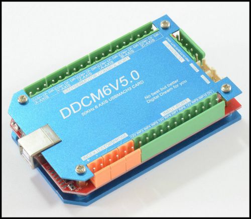
1. Products brief introductionDDSMXV5.0 is designed by our Studio,it is a CNC system based mach3.It’s version is 5.0 now.You do not need to add other Hardware,and you can complete the signal conversion from the G-code to the movement of the stepper motor drive control. This card is compatible with most stepper drives and servo drives. And it is perfect weapon to replace mach3 parallel interface board. DDSMXV5.0 include DDSM3V5.0,DDSM4V5.0,DDSM5V5.0 DDSM6V5.0,they are 3/4/5/6 axes mach3 CNC card. These 4 cards use the same Hardware platformDDSMXV5.0.They are limited to 3/4/5/6 axes for different voice of customer .They use the same manual. 2. Computer system requirementBasic Configuration:1) CPU: 1GHz; 2) Memory: 512MB 3) 500MB Available disk space 4) USB 2.0 Recommended configuration: 1) CPU: 2GHz Dual Core; 2) Memory: 2GB; 3) 1G Available disk space 4) USB 2.0 3.Production appearance and size1) USB communication interface, and power supply for the board; 2) 10 IO input, opto-isolated, It Can be configured to limit the emergency stop and other functions, all of them are 2edg port. 3) 3IO output with opto-isolated for spindle which can be set to M3,M7,M8,etc. 4) Up to 6 axes stepper-motor control port. Each port has up to 50KHz plus output; 5) COTEX-M3 of NXP-LPC is main control chip; New feature:6) New design Aluminum shell make the system more stable; 7) This system is equipped with RS2332 manual control box. You can use manual control box with this port. 8) Spindle control port with voltage Mod (0-10V). 9) Spindle speed feed back port-INDEX. 10) There is a power autostability system. When USB port overvoltage or undervoltage or within other EMI, this system can make power of system stable. 11) There are High speed interface chips,which make stepper driver signal more stable. 12) There is a USB protection chip,which can protect system within high voltage EMI. 4.Detailed functional introductionA System input voltage 5V B. Operating voltage of input interface with no opto-isolated:5V C Operating voltage of input interface with opto-isolated:12V D Operating voltage of output interface:5V E stepper motor control signal output voltage:5V F Spindle Signal: 10V 5.Functions and define of each module:
|
Engine Components for Sale
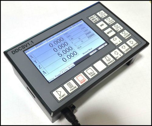 Ddcsv1 4axis 4linkage motion controller stepper motor and servo motor cnc driver(US $200.00)
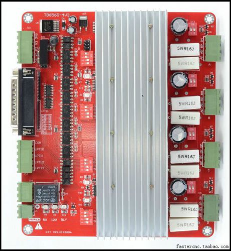 Cnc 4 axis tb6560 2.5a stepper motor driver controller board(US $50.00)
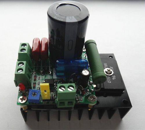 Motor speed driver controller mach3 spindle governor(US $15.00)
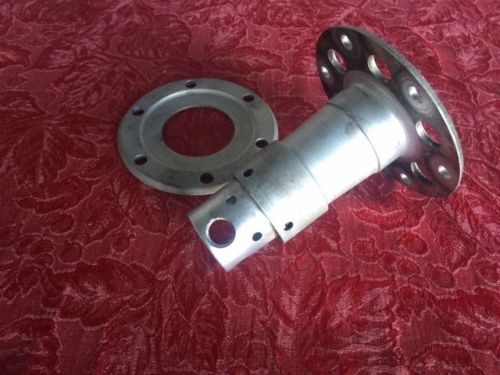 Continental c-85 propeller hub - complete p/n 3745 with flange pin p/n 3991(US $900.00)
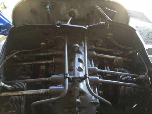 Lycoming 320
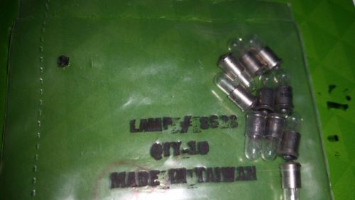 10 ea lamp bulb p/n 8628 sealed(US $6.56)
Chevrolet Trax (2007): infomation
Thu, 29 Mar 2007By Liz Turner First Official Pictures 29 March 2007 09:09 Chevrolet Trax: the lowdown How low can you go in the US? That’s the question three compact concepts are asking the public at next week's New York Motor Show. GM revealed just one of the minicars today - this cute, four-door Trax.
Ford dumps the CD player
Tue, 26 Jul 2011CD Players in Ford Cars are no more I’m not old enough to remember when cars came with valve radios, but I am old enough to remember when many cars didn’t even get a radio. I’m also old enough to remember when the music source of choice in a car was the 8-track tape machine. And actually, for in-car use, 8-tracks were great.
Bugatti reveals one-off ‘Sang Bleu’ at Pebble Beach
Fri, 14 Aug 2009Bugatti is celebrating its 100th anniversary with yet another one-off Grand Sport, called the Sang Bleu. It was revealed Friday as part of festivities for the Pebble Beach concours weekend. It’s a two-tone car, but paint is not the secret.